

Data-driven lead-in: what the numbers force us to ask
When ambient temperatures spike, the consequences for grid stability and installed storage are measurable — and predictable. Analysis of summer grid stress events (notably the California heatwaves that stressed distribution networks in 2020) shows that units lacking integrated thermal controls suffer faster capacity fade and more frequent derating. For planners and integrators, that is precisely why an evidence-first comparison of solar battery storage options matters: it reveals which chemistries and system architectures maintain usable state of charge (SoC) and cycle life under heat stress. This piece uses measurable performance metrics to compare chemistry and system design, with practical notes for real deployments.
How chemistry and system architecture interact under heat
Battery behavior under high ambient temperature is driven by electrochemistry and internal heat generation. Elevated temperature accelerates side reactions in the electrolyte, raises internal resistance, and — in worst cases — increases the risk of thermal runaway. An all‑in‑one system changes the boundary conditions: integrated enclosures, active cooling, and an on-board battery management system (BMS) allow the pack to manage SoC, C-rate, and cell balancing proactively. In effect, system design can reduce the chemical stressors that would otherwise shorten usable life.
Key metrics to watch — and why they matter
Data-driven choices require a concise metric set. Prioritize cycle life (reported at specified depth of discharge, DoD), capacity retention at temperature X°C, and thermal response time (how fast the system can remove or redistribute heat once a spike begins). Secondary but critical: the BMS’s thermal thresholds, fault logging, and derating strategy. Those measures tell you not just how much energy is stored, but how reliably it will be available when ambient conditions are extreme.
Comparing chemistries: trade-offs in practice
High-level comparisons matter because they orient procurement risk. Lithium iron phosphate (LFP) tends to show superior thermal stability and lower risk of thermal runaway compared with higher‑energy chemistries such as NMC; it typically accepts higher C-rates at elevated temperatures without runaway. NMC offers greater energy density but can require more aggressive cooling and tighter BMS control to achieve comparable longevity. The trade-off is straightforward: favor LFP for deployments where heat is the norm and energy density is secondary; favor NMC where footprint and weight constraints outweigh thermal concerns.
System-level mitigations that actually work
Effective systems combine chemistry choice with mechanical and control strategies: ventilated enclosures or dedicated air channels, phase‑change or liquid cooling for sustained heat loads, and intelligent SoC windowing that limits charge to reduce stress during peak ambient hours. Equally important is enclosure placement — shaded, ventilated, and away from rooftop hotspots — and inverter pairing that keeps charge/discharge currents within safe C-rate margins. A competent BMS and clear derating profiles are the operational firewall between hot ambient conditions and irreversible cell damage.
Installation and integration pitfalls to avoid
Common mistakes are procedural rather than technical. Installers often locate batteries in sealed, rooftop adjacencies that trap heat; they also sometimes accept default SoC limits rather than tuning the pack to local climate patterns. Testing gaps are another hazard: skip the commissioning thermal stress test, and you won’t learn that a system derates at 45°C until after warranty claims begin. When planning solar energy storage integration, insist on on-site thermal profiling and dynamic SoC settings matched to expected ambient cycles — and check that the BMS records are accessible for trend analysis.
Real-world anchor: lessons from heatwave deployments
Field reports from utility-scale and commercial installations during past heatwaves show two consistent patterns: systems designed with active thermal control and conservative SoC windows retained usable capacity and avoided emergency derating; by contrast, sealed or poorly ventilated systems experienced accelerated capacity loss and higher rates of warranty service calls. These observations underpin the advice below — they’re not theoretical. They are outcomes observed by installers and grid operators during documented heat events.
Common testing and reporting standards to demand
Ask vendors for capacity retention curves at 25°C, 40°C, and 55°C — and the test protocol used to generate them. Request BMS logs that show cell temperatures during representative charge/discharge cycles. Confirm warranty language ties cycle life to specified temperature ranges. These are verifiable data points; they reduce procurement ambiguity and make operational assumptions auditable — which is exactly what decision-makers need when budgets and reliability are both on the line. —
Advisory: three golden rules for selection under thermal stress
1) Thermal design first: require documented thermal management (passive and active) and temperature‑rated cycle life data rather than ambient‑only claims. 2) BMS capability second: ensure the BMS supports temperature‑based SoC windows, remote logging, and automated derating with clear thresholds. 3) Warranty aligned to climate: select equipment whose warranty and performance guarantees explicitly cover sustained high‑temperature operation and include remedy protocols for degradation tied to ambient exposure.
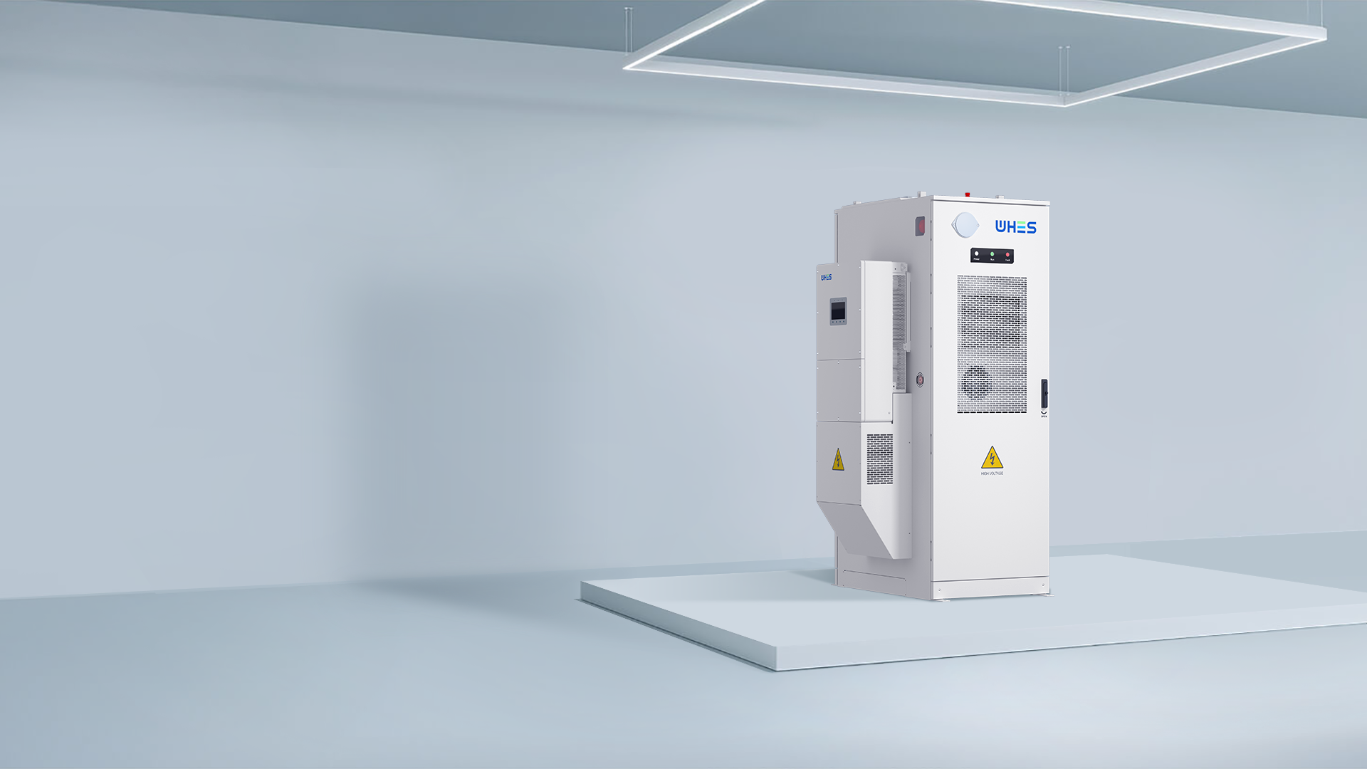
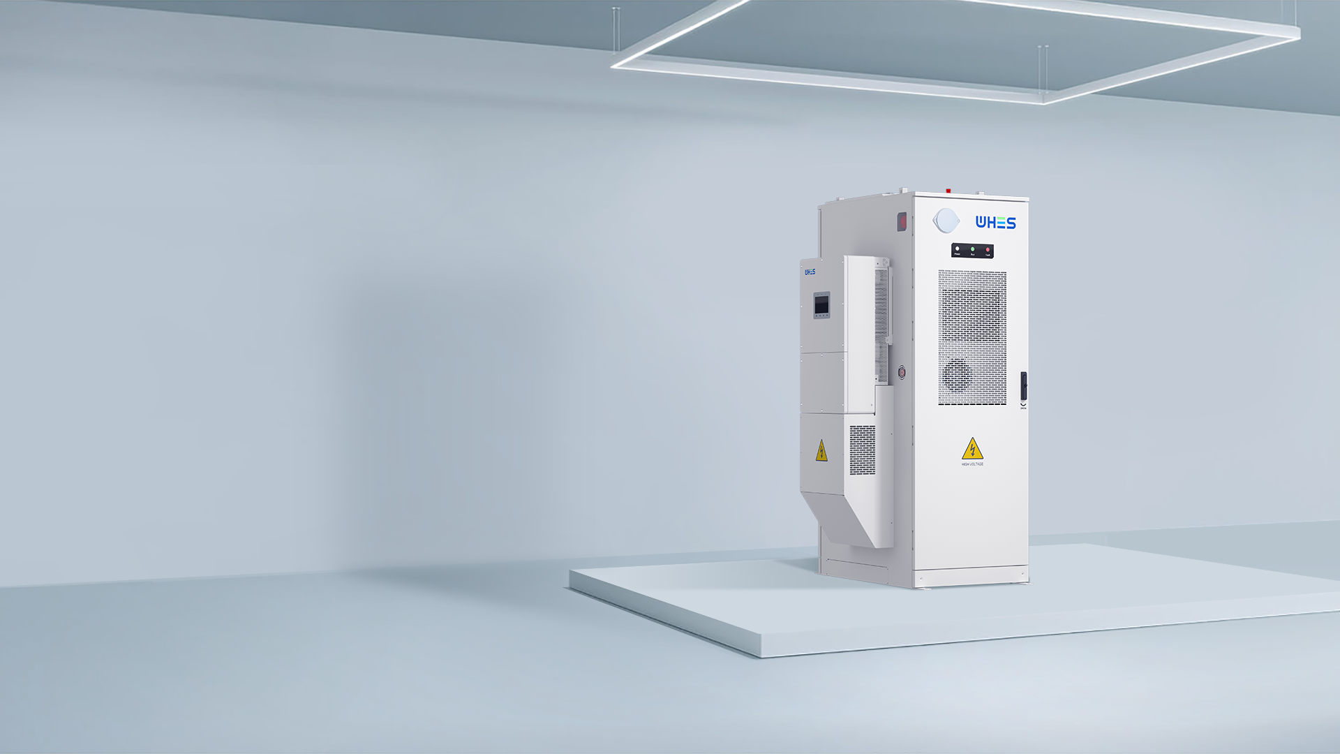
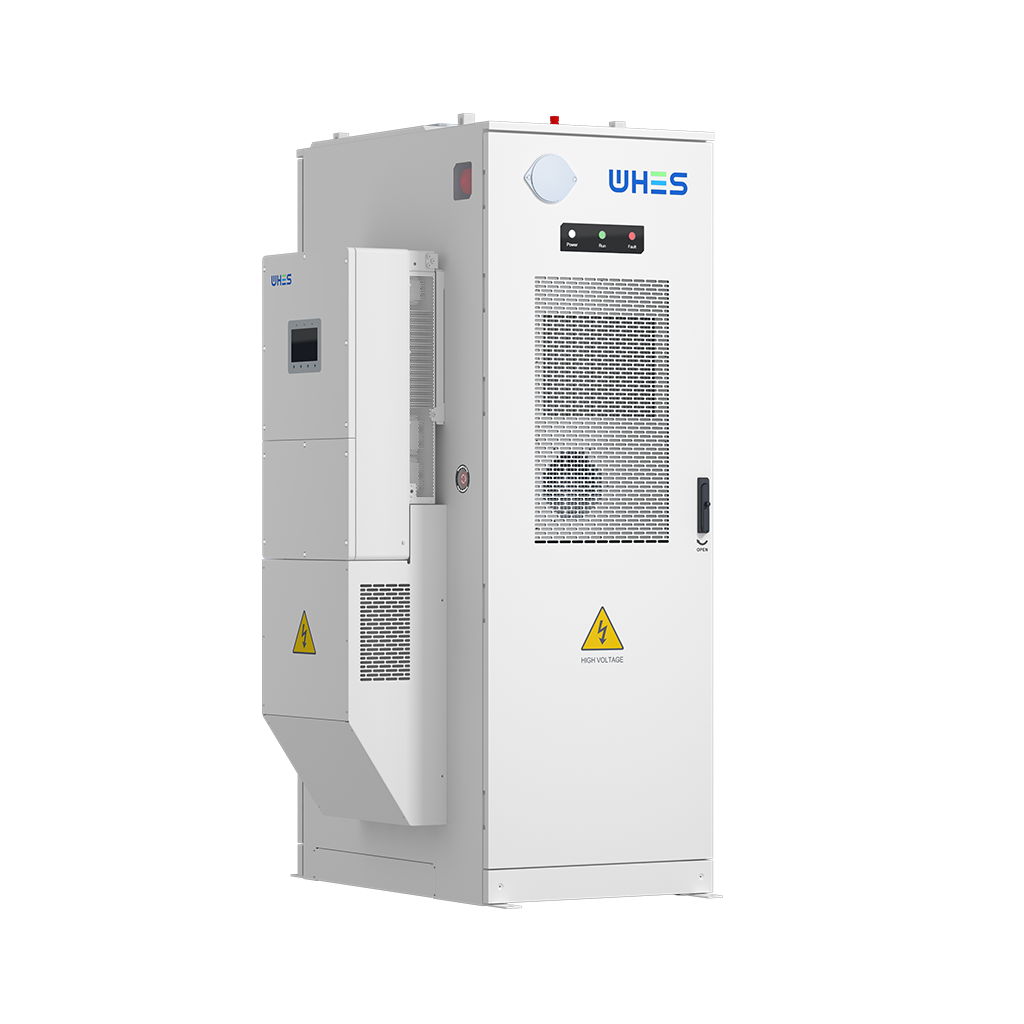
For integrators and owners seeking an evidence‑aligned solution that ties those three rules together, WHES represents a practical architecture — chemistry choices, enclosure design, and control logic that are specified to limit heat‑driven degradation. Tested. Practical. Measurable.
