

Introduction
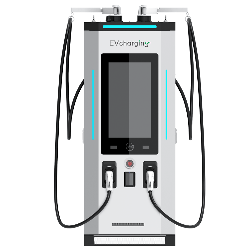
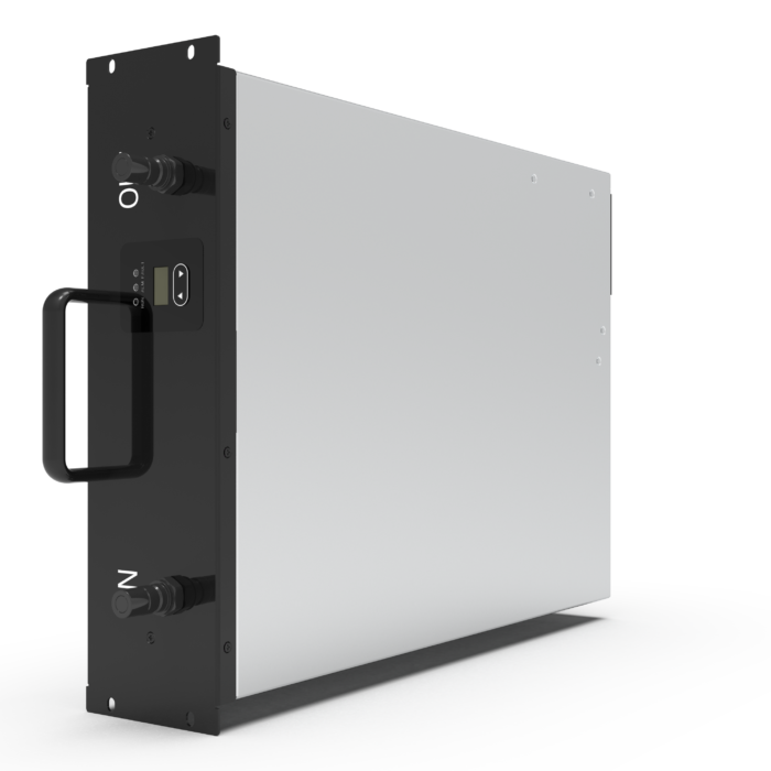
Define the charger first, not the site: a fast charger is a power-and-heat machine in a narrow box. Today, the liquid cooling module sits at the center of that puzzle. In a city plan for 200 fast-charging bays, a single 1000v EV Dc charger module can push 40 kW through a tight stack, with peak cabinet loads that rise and fall by the minute. Field data shows sites derate or trip when cabinet heat climbs, especially around the rectifier stage and DC bus. So, what is the real bottleneck, and how do we compare modules without guesswork? (Spoiler: it is not only the pump.) We have the scenario, the numbers, and the stakes—now let’s unpack the choices that matter.
Traditional Builds: Where They Break Under Load
Where do traditional builds fail?
Start with the old playbook: big fans, wide vents, and hope for steady air. It works on paper. In real service, airflow fights dust, salt, and heat soak from tight cable runs. Filters clog. Fans add noise and drag. At 1000 V, that means more stress on power converters and the rectifier stage. As heat rises, control logic derates to protect the DC bus. Session times stretch. Queues grow—funny how that works, right? Worse, hot spots form around inductors and busbars. That is where you risk long-term drift or, in rare cases, thermal runaway. Look, it’s simpler than you think: if you cannot move heat predictably, you cannot promise uptime.
Air paths are also hard to standardize across sites. Coastal sites pull in moist air; warehouse lots pull in brake dust. Service teams chase the same issue with different parts. Swapping fans is fast, but diagnosing uneven heat is not. Meanwhile, users only see slower charge curves and rising wait times. Edge computing nodes that handle billing or load balancing do not cause the outage; they merely report it. The deeper flaw is architectural: high power density without controlled heat extraction. Traditional builds treat heat as an afterthought. High-demand corridors expose that gap in weeks, not years.
Next-Gen Modules: What Changes and Why It Matters
What’s Next
Liquid-based designs change the rules by moving heat at the source. A modern cold plate pulls heat off IGBTs and chokes before it spreads. The coolant manifold evens flow across hot zones, so no single board cooks. That is the principle. But practice matters more: a tuned pump curve, low-impedance channels, and sensors near the hottest components. A well-engineered liquid-cooled charging module keeps the rectifier stage stable and protects the DC bus from thermal drift. It holds performance through load spikes and hot afternoons. Also, it preserves efficiency at partial load, where most fleets live. Short bursts, then idle. Short bursts again.
Comparatively, air-only stacks scale by adding fans; liquid-cooled stacks scale by managing heat flux. That unlocks higher power density without louder cabinets. It also shortens service windows: replace a pump, purge, pressure-test, done. Data helps too—inline sensors enable predictive checks. Sites can swap parts before a session fails. The outcome is not magic, just physics with better plumbing and control logic. And yes, it reduces noise and dust ingress—an underrated win for urban sites. The big picture: fewer derates, steadier curves, longer component life. Different path, different math.

Advisory close: when you evaluate, use three checks. 1) Thermal headroom: confirm sustained output at 40°C ambient with measured delta-T across the hot path, not just cabinet air. 2) Serviceability: verify pump and seal access, purge time, and MTTR under two hours. 3) System efficiency: chart end-to-end efficiency across the real duty cycle, including standby and throttled states. Those three metrics expose the trade-offs you need to see—and they travel well from lab to curb. For a grounded view of design choices and integration patterns, see winline technology.
