

Introduction: Scenario, Data, Question
Have you ever watched a shop floor stall because two spindles couldn’t talk to each other fast enough? I have — and it’s maddening. A typical double spindle CNC machine can, on paper, double throughput, but real-world production often falls 20–40% short of theoretical capacity (shop-floor audits, 2024). That gap raises a question I keep asking teams: where does the promise of parallel turning turn into parallel friction? I want to walk through a scenario: two operators, the same program, yet one setup meets cycle-time targets and the other doesn’t. The variables? Synchronization, tool paths, and sometimes a timid control configuration. These are not mysterious faults; they’re patterns we can spot and fix. So — what exactly breaks down, and how do we decide which fixes matter most? Let’s move from the problem to what’s underneath.
Traditional Flaws and Hidden Pain Points
Why do these systems stumble?
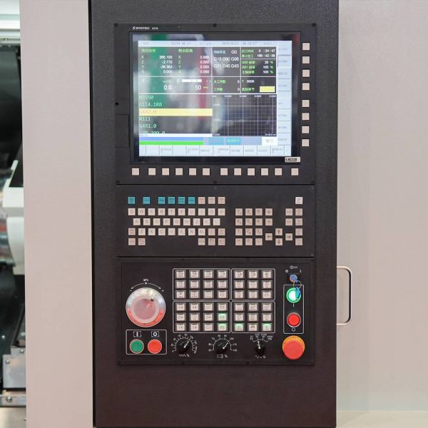
I’ll be direct: many shops treat a double spindle cnc lathe like two single spindles bolted together. That’s the first flaw. In practice, spindle synchronization and coordinated axis motion require tuned control logic, precise axis encoder feedback, and reliable tool changer routines. When those elements are weak, you see chatter, missed registers, and wasted cycle time. Look, it’s simpler than you think: poor encoder calibration or laggy servo turret responses can turn a job that should take 12 minutes into 18. I’ve seen this repeatedly — and each time the fix was a mix of settings and modest hardware checks.
Hidden pain points are often human or procedural. Operators unconsciously favor safety margins in feed rate because past runs faltered; programmers add extra dwell times to compensate for unreliable C-axis indexing. Those decisions cascade. The control system may allow high feed rates, but coolant pump performance, cutting torque limits, or workholding rigidity cap real gains. — funny how that works, right? Addressing the pain means pairing concrete measurements (encoder error, torque curves) with simple rule changes on the shop floor. Industry terms you’ll want to track: spindle synchronization, axis encoder, feed rate, and turret indexing.
Comparative Outlook: New Principles and Practical Steps
What’s Next — Principles to Adopt
Moving forward, I compare two routes: incremental tuning versus system-level redesign. The incremental path tightens servo gains, refines tool paths, and enforces stricter setup checklists. It’s practical, lower cost, and I often recommend it first because it delivers measurable gains quickly. The system-level route leans into smarter controls, edge computing nodes for real-time analytics, and predictive power converters that stabilize spindle power under load. Both paths matter; your choice depends on volume, part complexity, and budget.
For a practical view, consider upgrading control logic to enable true synchronized camming between spindles. That alone can shave seconds per part across thousands of cycles. Also, integrating low-latency monitoring (axis encoder diagnostics and spindle torque logging) helps you stop guessing and start tuning based on data. I’ve run trials where simple telemetry cut scrap by nearly half. The point is: combine better control algorithms with real observations. You’ll see gains. — and yes, some investments pay for themselves within months.
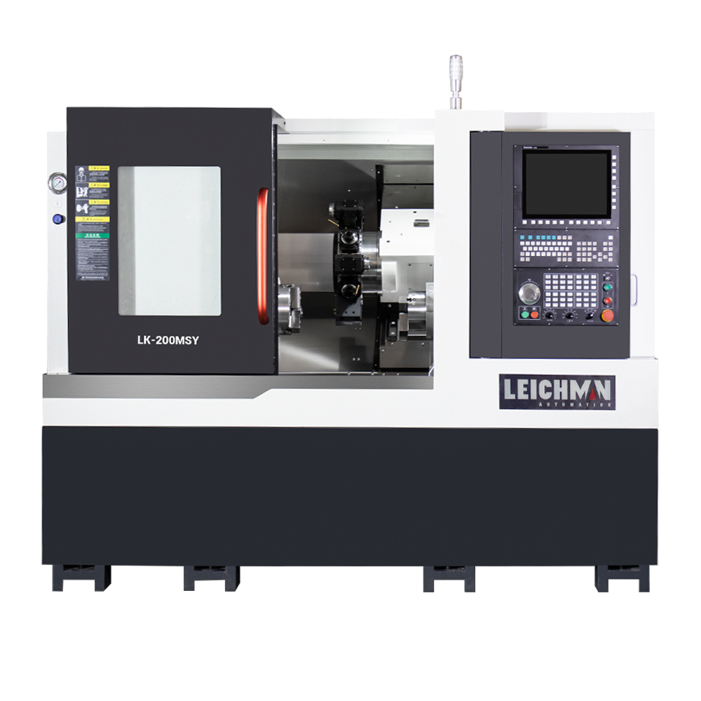
To wrap up with actionable help, here are three evaluation metrics I use when choosing solutions: 1) Cycle-time delta per part under identical tooling, 2) Mean time between stoppages (MTBS) for synchronized operations, and 3) Percentage of programs needing manual dwell or slow-down edits. Use those numbers to compare vendors and upgrades. If you want to explore machines or controls that make these steps easier, check out practical models from Leichman. I’m happy to dig into examples with you — we can compare notes and run a quick checklist together.
